Home
Repair And Restoration
CB500X OP (Power) Plugs
Guide Date - 07 March 2017
By Ren Withnell
OP? OP means "Option Plug" apparently. The idea is these plugs allow owners to connect stuff to the electical supply of the motorcycle.
There is one under the seat with 2 wires, positive and negative. In this position I'd expect this one to be used for maybe charging a mobile phone under the seat, extra lighting at the rear or putting power into a top box or pannier for whatever purpose.
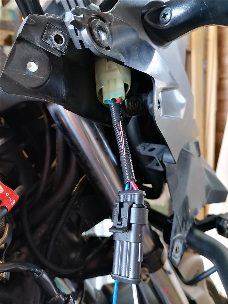
The other plug is tucked tightly in the fairing near the digital speedo. This has 3 wires, positive, negative and "high beam". This could be used for handlebar mounted GPS, extra lighting and charging in a tank bag perhaps. The 3 wires means additional lights can be switched between dipped and main beam.
The Rear Plug
This is the easy one and is found under the seat as shown below.
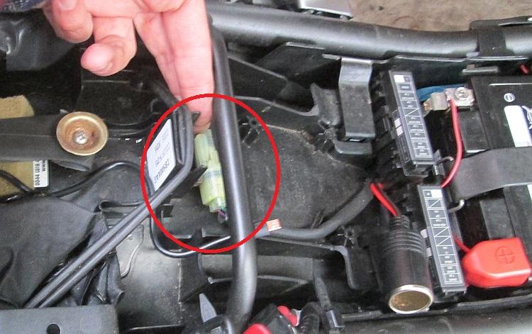
There it is...
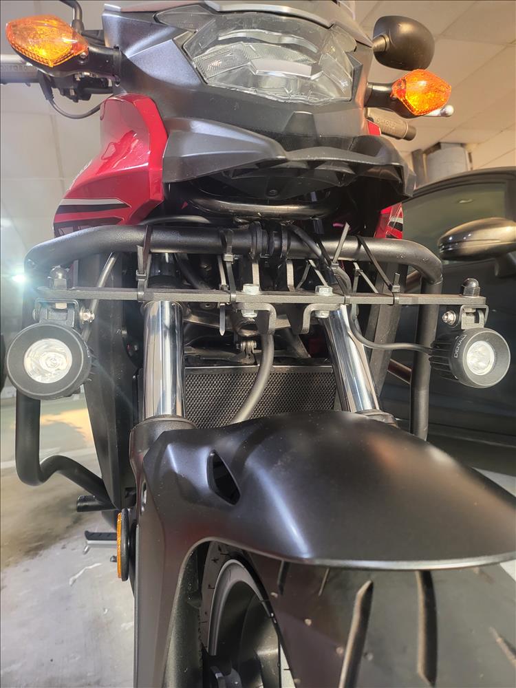
Front Plug
Getting to the front plug is a whole different ball game. To access this you will need to remove the side panel and then remove the fairing panel. Once this is done the plug is tucked up beside the clocks to the right hand side.
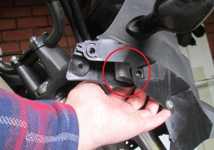
It's tucked right up there.
By removing the fairing this will allow some degree of acces. However - very limited access. You can get in there to unclip the empty connector (I'll explain later) but my fidgy fingers could not get it back in. To make life easier you will need to remove both sides of the fairing and then remove the plastic trim or shroud around the clocks. This makes accessing the front option plug quite a task.
Empty Connector?
Both the front and rear OP come in 2 parts. On side is already wired up and ready to go, the side connected to the bike's electical circuits. There's a corresponding piece that mates with the wired side but has no wires or connectors in there, just rubber bungs to keep the muck out.
The idea is that you are expected to source and terminate the connection yourself. I *HAVE NOT* done this myself although I may do in the future. From the fabulous CB500X.com comes this link to a site that appears to sell similar connectors with the terminals required. Again I cannot vouch for this but it looks right.
http://easternbeaver.com/Main/Elec__Products/Connectors/Sealed/SM-HM/sm-hm.html
So that's the option plugs. I'd love to hear from anyone who's used these option plugs. I'd like to know if any other motorcycles also offer something similar, I'm sure some do.
Reader's Comments
Allan Wright said :-
Hi and many thanks for your article
i have a 2019 CB500X
Q: what colours are the Live and earth for the 2 pin under the seat (i was thinking to cut the connector off and connect wires via posi connectors to usb holder for the sat nav connetion
do you consider this connection (under seat OP) is ok for sat nav connection?
i would rather not try and find the front OP as you advise quite difficult
REITERATE THANKS FOR ARTICLE
30/03/2020 05:33:48 UTC
Ren - The Ed¹ said :-
I'm not going to state the colours because I do not have either a manual or ownership of the 2019 version and I don't want to give you false information. It would be a trivial task to work out positive and negative with a multimeter. On my own 2016 and 2018 models I have used the underseat options plug to charge up a powerbank at 2 amps so I'm sure that would be sufficient to run a sat nav!
30/03/2020 08:27:05 UTC
allan wright said :-
many thanks Ren
roger that with multimeter (will do)
appreciate your response re:sat nav conn.
stay safe in these troubledC19 times
BR
30/03/2020 12:34:38 UTC
Ren - The Ed¹ said :-
Cheers Allen. Just be sure to get the wires the right way around. It won't do any harm to try charging an old phone or similar before you fry the sat nav
01/04/2020 09:54:48 UTC
D Brewer said :-
I recently added some Denali lights via the front OP plug, I took some pictures I could send if you'd like some better quality ones for the article. I found a corresponding female plug connector complete with terminals and seals on eBay, which I used with a Superseal connector to extend the three wires where either I, or a future owner could more easily attach and detach wiring in the future as the access as you point out, is terrible, I actually cut that vinyl boot to improve access as I cannot see its purpose, it doesn't seal anything and is only there I assume to stop the loose connector rattling against the fairing.
 13/02/2021 19:16:19 UTC
Ren - The Ed¹ said :-
Thanks D Brewer. It's a smart idea to extend the plug into a more accessible place. What draw are you putting on the wires? Since I wrote this article I've seen discussions about not drawing too much as the circuit somehow, some way, puts a load on the LED headlight module. This, well, this clearly demonstrates my lack of knowledge re LED lighting but I'll add a link to the CB500X.com forum where this is mentioned.
https://www.cb500x.com/index.php?topic=7109.0...
14/02/2021 19:37:44 UTC
Kerry said :-
Stick a relay in for additional lights.Take 12v coil trigger from existing light connector (draw off circuit in negligible milli amp range). Supply it's working load (in the amps range) switching side direct from 12volts supply (battery positive will do). And stick a 5 amp fuse in line as close to the supply as possible. Otherwise risk frying some very expensive/piss delicate modules. Use appropriate thickness wires....If not sure size upwards.
14/02/2021 23:00:18 UTC
Ren - The Ed¹ said :-
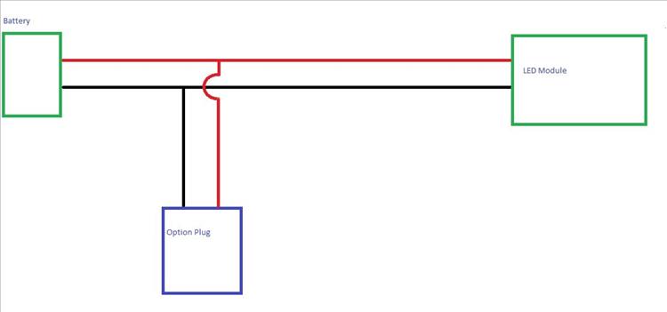
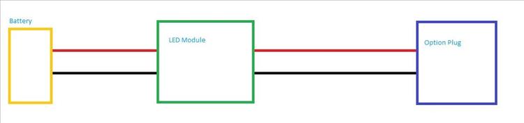
This only proves my ignorance - what I don't understand is how the LED module would get fried.
I imagine the circuit would be as pictured. This would mean any more electrons, angry pixies and current buns flowing through the wires wouldn't have additional effect on the LED module.
 15/02/2021 09:20:59 UTC
Ren - The Ed¹ said :-
I know I'm massively oversimplifying but if the LED module is affected I figure it's wired thus.
 15/02/2021 09:24:11 UTC
said :-
You are good with your leccy there ren. Where I'm coming from is your 2nd drawing. These modules are not built to mil or airspace standards. IN cars bmw FRM modules frequently fail when the battery either flattens or is changed. The same for Merc SAM modules. Even Tesla are now claiming their touch screens have an expected life of 6 years and claim that the electronics are a wear item like brakes that are uneconomical to manufacture to a level that would last the life of the car...your first drawing is way to go. I know a auto electrician who won't use manufacturers diagnostics on Audi VW cars to activate fog lamp option when wiring in after market fog lamps instead he wires them independent of the cars CAN system. A bit old hat but this lad knows his stuff and has had tidied up a few dealer disasters from the 'tic the box' dealer instal.
15/02/2021 11:50:22 UTC
Kerry said :-
Forgot username on comment. Sorry. This lock down is cracking me
15/02/2021 11:57:25 UTC
Ren - The Ed¹ said :-
I'm glad you appreciate my insightful technical drawings Kerry, although I suspect there ought to be an air of irony somewhere.
The NOTION of a CANBUS makes a lot of sense to me coming from a computer networking background. This idea that there's a loop of wires (+ve, -ve, data +ve, data -ve) running around the car/bike once should really simplify wiring. Put each item on the CANBUS with an ID code then say "rear taillight ID334332, on". Simples. The reality seems quite different though. Bespoke software without access save for costly main dealers. Items (modules ie rear taillight) being both costly and poorly executed. Without access to the main computer no ability for regular folks to say "ID443998 is now your taillight".
What strikes me is there *could* be a market for open source CANBUS systems, much like Linux on servers and PCs. Manufacturers would make money on selling you the brain and the various modules but you'd be able to fit them yourself and get into the code to make the necessary changes as required.
If I had the time and the knowledge and the help required it would be a fascinating project to create an ECU for a simple bike like my CBF125 - using a Raspberry Pi.
15/02/2021 14:46:30 UTC
Kerry said :-
No irony here.I like good simple drawings . Plenty of merit in your open source CAN bus idea you could say add function like activation of hazards under severe braking. The thing is that CAN bus. if installed well should improve reliability and diagnostics possibilities. But a motorcycle is probably the hardest environment for electrics/electronics/and in particular connectors.
15/02/2021 18:25:57 UTC
Borsuk said :-
Why would anyone wire the options plug in series with an electronic lighting module.
16/02/2021 00:31:19 UTC
Ren - The Ed¹ said :-
The advantage of a CANBUS system on a motorcycle (subject to previously mentioned quality problems) would be simpler, fewer and more robust connectors. Rather than a myriad of messy wires and connectors all over the place there could be a standardised connector and fewer of them. Heck, think about it! If it were a bus system there would be simple patch leads between all the modules. Some short, some long depending on the locations on the bike BUT you could have one long patch lead under the seat and just swap out leads till you find the dodgy one. Use that lead until you can get a replacement of the right length. The more I think about it, the more I like the idea.
Borsuk - I/we are not saying this is definitely absolutely the way Honda has the LED module set up - but yes if it IS wired that way then someone somewhere needs a jolly good telling off.
16/02/2021 09:20:26 UTC
D Brewer said :-
Hi Ed,
I don't actually know what the draw is without connecting a multimeter in series, but my guess is low, the Denali harness is wired directly to the battery, and the blue high beam trigger wire as well as the wire for the constant live is pretty skinny so I think all it's doing is providing a current to switch a solid state relay since I don't hear any clicking from the Denali relay unit when the high beam is triggered.... I'm guessing that because there is a ground, live'high beam plug up front that it is there to power optional lights from factory, perhaps the people who have had failures have been powering their lights from the Hugh beam trigger wire on it's own?
19/02/2021 18:19:04 UTC
Ren - The Ed¹ said :-
Thanks D Brewer. I reckon you're right, the Denali is using the options plug merely as a signal to switch on and high beam etc. Yes it appears if you were to put a wire from the options plug straight to a powerful (say incandescent) bulb you'd be at risk of frying something.
Hay carumba! I've just had a look on the Denali website. I guess their stuff must be good cos it sure ain't cheap.
20/02/2021 09:59:03 UTC
D Brewer said :-
Absolutely, they are expensive, I couldn't justify the hike to the next light up, but what really sold them for me was the possibility to have the lights at 50 and 100 percent on the dip and full beam respectively, I went for a bit of a quick test run the other night and was able to carry a lot more speed through the corners, I really like them, plus the install is super easy, it's just a case of good cable routing and tidying everything away....
01/03/2021 00:04:57 UTC
Ren - The Ed¹ said :-
Which Denali lights have you got D Brewer?
01/03/2021 17:38:26 UTC
D Brewer said :-
Ren, I have the S4's with the data dim module installed.
01/03/2021 18:43:34 UTC
Ren - The Ed¹ said :-
So - from what I can work out on the website you buy a kit and the "option" of a datadim module. The datadim taps into the high/low switching and when on low drops the S4's intensity by 50%.
02/03/2021 07:51:56 UTC
D Brewer said :-
Yeah, it's an add in box that replaces the standard relay module, plug and play. The standard wiring kit just has an on/off switch at the handlebar.
05/03/2021 16:58:09 UTC
Ren - The Ed¹ said :-
Are the lights with the datadim switched? What I mean is along side the 50% reduction on "dip" is there also a separate handlebar switch?
05/03/2021 20:13:29 UTC
Sara said :-
I bought a cb500x bike with nice auxillary Denali lights but after I installed crashbars they won't work. Where do you think the wirings were most likely disconnected from? I dont know where to look--
 17/04/2023 03:45:06 UTC
Ren - The Ed¹ said :-
Hi Sara. My first place to look would be the options plug behind the front fairing. If you look at the images the original article at the top of the page it's the second image under "Front Plug". Then I'd check out the one under the seat, "Rear Plug". If not all you can do is trace the wiring from the lights.
Good luck!
17/04/2023 08:28:37 UTC
András said :-
Hi Ed, I am thinking myself on buying the S4 Denali kit for my 2022 CB500X.
My question is how exactly I "taps into the high/low switching"? Could you pls ellaborate?
Thank you
24/08/2023 22:52:41 UTC
Ren - The Ed¹ said :-
Hi Andras. The plug behind the upper fairing has 3 pins - one for ground, then a positive for low beam and a positive for high beam. BUT BUT BUT!!! It has been noted by other CB500X owners that you do no simply connect powerful lights to these wires. I do not understand the technology but it's something to do with burning out the controller.
Look further up the page to D Brewer's comment and my comment below.
I'm no expert, what I do know is you need to do more thorough research before you make an expensive mistake.
25/08/2023 07:50:44 UTC
Upt'North ¹ said :-
András,
You're probably not going too.....but......don't wire these up without a relay or dedicated motorcycle accessory block. The blocks can have fuse and relay protection for each circuit.
I think Denali make one but there's lots out there, Motor Cycle Sport and Leisure recommended one years ago, but I can't recall the make now. It'll be on the interweb thingymabob somewhere.
Upt.
25/08/2023 08:48:45 UTC
Upt'North ¹ said :-
This sort of thing.
I apologise if I'm covering old ground ( pun intended ) on this thread, I haven't read it.
https://www.visordown.com/news/product-news/first-look-pdm-60-power-distribution...
25/08/2023 10:11:54 UTC
said :-
Thank you Ed and Upt'North. Will dig deeper. The question came as this guy who sales Denali in the UK shows this in his video, but just does not o into detail. As far as I can tell there is some kind of relay included in the bundle, but i don't know if its enough or the right one.
https://www.youtube.com/watch?v=U_tY7nwAhbk
27/08/2023 12:28:12 UTC
said :-
27/08/2023 12:28:22 UTC
Upt'North ¹ said :-
András, I should have said, I'm an electrical idiot.
I just follow the instructions and it seems to work out.....most of the time.
I just wired a Garmin Sat Nav in, I made the mistake of asking (elsewhere) how to do it. In the end I just did it Garmins way, it worked, the sun still came up (briefly) and all's good.
Good luck.
Upt.
27/08/2023 13:47:09 UTC
nab301 said :-
As far as I can see , with the S4 kit you need to specify the following (as extras) when ordering. The Dual intensity controller ( Relay) and the Switch Eliminator . Then the blue lead is connected to the high beam lead and this uses minimal current to switch the relay , ( dual intensity controller). If you email the guy via the website I'm sure he will explain everything!
Nigel
28/08/2023 13:08:26 UTC
FR_TX said :-
Denali has a Datadim Dual Intensity Controller, that connects directly into the forward aux port (using the appropriate wiring harness), which allows to control the auxiliary lights using the main high beam switch. Or you can find similar relay/controller modules.It is never recommended to connect auxiliary lights straight into the aux port.
06/12/2023 05:53:59 UTC
Ren - The Ed¹ said :-
Good info, thank FR_TX. I had a quick look on the Denali website... OUCH! Their stuff best be good because it sure ain't cheap.
06/12/2023 20:10:31 UTC
Name
Comment
Add a RELEVANT link (not required)
Upload an image (not required) -
Uploading...
Home
Repair And Restoration