Home
Repair And Restoration
Aftermarket Alternator Stator CBF 125
Job Date 05 December 2016
By Ren Withnell
After the lights went out on the venerable 125 (CBF 125 No Lights - Again) I have decided I am going to risk purchasing an aftermarket stator. A genuine Honda one can be found for between £115 and £170 if you trawl the interworldwidewebnet for long enough. The aftermarket item comes in at the princely sum of £70.
The images on Ebay look right. The wiring looks right. The code the advertiser is using is the same as the OEM code (31120-KWF-941) so I figure it will at least fit.
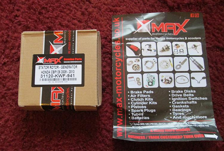
It's here! But what is inside?
The part is here and it looks OK. It *feels* just oh-so-slightly less, er, errr, something, errrm, I dunno, it's very very subtle, it's only just slightly less...erm...quailty? The difference is so marginal it's visceral and subconscious. I was going to say it's like getting out of a Mercedes into a BMW but that is still too large a gap. Fitting the new stator is once again *almost* as easy as fitting a genuine item. Everything lines up, everything fits but the rubber seal around the wires is just a smidgen tighter and there's just a hint more exposed wiring. I really really am splitting hairs that have already been split twice before. The quality appears fine.
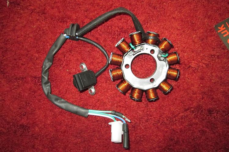
It's fine it really is. Everything is there just as it should be.
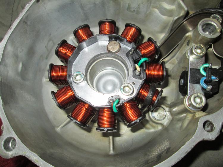
It fits well and we're almost ready to roll.
Before I replace the stator back on the bike I check out the regulator rectifier. This is a "black box". That isn't to say the regulator rectifier is actually black, I use the term "black box" to suggest there's no way to get inside it to see if anything is broken or to fix it. All I can check is the connector. The connector doesn't look too healthy, particularly the big red/yellow positive feed to the battery. It has good continuity but the corrosion around it indicates this might not be the case for too long. The wire has been hacked in the past too by some big ape. Oh, that would be me...
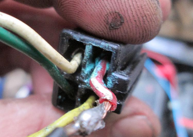
It still works but it doesn't give me that nice warm feeling.
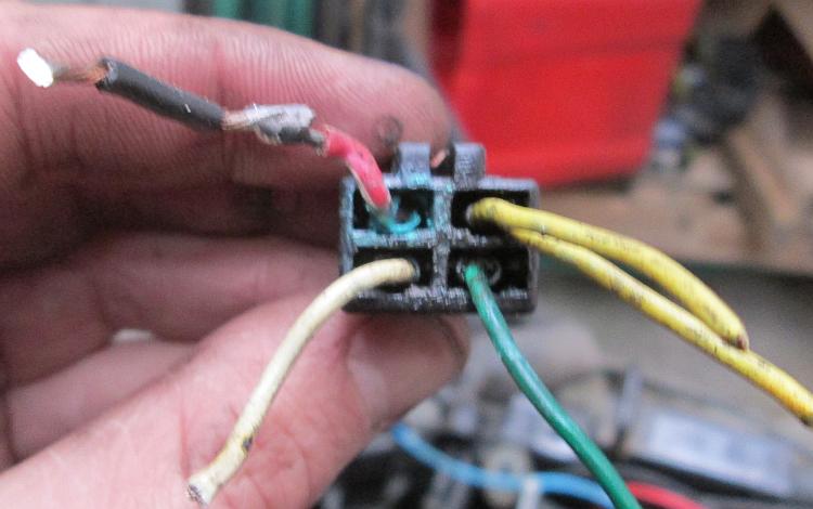
This is for my records, so I know what wire went where.
The wires come out of the connector block at a sharp angle and there's signs the wires are rubbing on the inside of the plastic rear cowl. Why oh why oh why do I have to do Honda's long term product testing?
I move the regulator rectifier to lesson the angle on the wires. I cut the connector block off and solder on some spade connectors. I hope the cowl will still fit over the jauntily angled reggy reccy. It does. I hope my re-routed wires don't rub against the cowl. They don't. I'm not happy that the spade connectors are not fully insulated so I make a note to purchase some and replace them in the future. Meh, they'll be fine as they are for now.
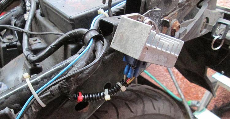
At this angle the wires are under less stress and the protective sheath no longer rubs against the cowl.
Oh that's better, there's plenty of room and no rubbing.
I pop the crankcase back on the bike and reconnect the 4 wires. I top up the oil to replace that which came out after opening the crankcase and start the motor.
LIGHTS! Well that's a great start, we have lights. They're bright too. The CBF 125's lights as explained previously run directly off the alternator (via the regulator rectifier) and when the engine is at tickover they go a little dim. They're not as bad as the early CG125s which became barely visible but it is noticeable. Now, even at tickover, they're bright. Hmmmmm.
I hook up the multimeter and at tickover I've getting 14.6 volts. Double hmmmmmm. I rev the motor and the meter tops out at 14.97 volts. Triple hmmmmm. Basic instinct suggests this is great! I've always been told modern systems charge at between 14 and 15 volts and I'm right in the ball park with these figures. However the voltage seems high at tickover. Normally I'd expect a motorcycle, particularly a small capacity motorcycle, to be barely charging at tickover. I am hoping to put together an article explaining why this could be a problem in the future.
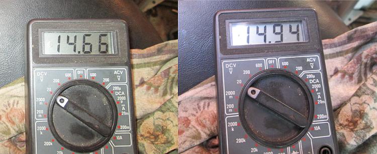
Tickover charge and revved up charge voltages. It's the tickover that seems a bit high.
So we're away! I hope the aftermarket alternator stator is sturdy enough to provide me with a further 30,000 miles worth of electrical energy, in fact I hope it provides 300,000 miles more but I doubt it. I hope my wiring hack is up to the task too. I hope my regulator rectifier remains in working order. I also hope too with a lot of learning to be able to bring you an article that actually explains how this little lot works. Don't hold your breath though.
Reader's Comments
Pocketpete said :-
All I need now is an article on how to adjust my chain. God I'm hopeless at mechanicals.
06/12/2016 12:03:12 UTC
Ren - The Ed said :-
Shall I do an article for you Pocketpete? Do you want video or text?
06/12/2016 22:35:25 UTC
Pocketpete said :-
Both and a spanner.
06/12/2016 23:13:24 UTC
Sharon said :-
I think a video would be great.
06/12/2016 23:13:28 UTC
Bob said :-
Check the battery voltage on ac with the engine running.
07/12/2016 12:27:13 UTC
Ren - The Ed said :-
Regarding the video...I'll see what I can do. Busy with real work at the moment do don't get too excited.
I'll do that Bob and let ya know what I'm reading. Cheers
07/12/2016 14:05:57 UTC
Ren - The Ed said :-
Just a note in case anyone's interested. Having covered 25 miles on the CBF 125 I checked the temperature of the regulator rectifier when I got off the bike. Touching the metal of the body I would say it felt warm but definitely not hot. Akin to touching a car bonnet after a gentle drive.
07/12/2016 15:10:42 UTC
Ian Soady said :-
Hi Ren.
I expect the hex head bolt in pic 3 replaces the socket head one you destroyed? I'd prefer to fit another socket head but then I'm a perfectionist (ironic laugh from my wife....)
That corrosion may be one of the reasons you were experiencing the original problems as it will cause a high resistance joint and could possibly cause the stator windings to overheat.
There's a goof fault finding guide on the link below (although that is the site that Bob suggested had an error in the description of the regulator function).
I would be quite happy with 14.6 volts at tickover but you may want to check the AC voltage across the output wires from the stator (disconnected from the reg/rec) which I believe should be around 20 volts / 1,000 rpm (although I'm no expert here).
www.electrosport.com/technical-resources/diagnosis-center/fault-finding-guide...
13/12/2016 11:47:24 UTC
Ian Soady said :-
ps like the picture of the thumb - mine look like that most of the time! I keep trying to remember to wear gloves but after all this time I usually just dive in.
13/12/2016 11:48:38 UTC
Ian Soady said :-
I also found this (link below) which, although the English is a bit idiosyncratic, seems to describe regulation via open circuit switching rather than switching to earth. But it's all a bit complicated for me.....
www.homemade-circuits.com/2012/10/motorcycle-full-wave-shunt-regulator.html...
13/12/2016 14:08:22 UTC
Ren - The Ed said :-
I used the hex head bolt rather than another socket head (allen) bolt for 2 reasons. Firstly I believe I'll be able to remove the hex head in the future. Secondly I didn't have any socket head bolts of the correct size. If this troubles your OCD I can edit the image to show a allen bolt?
I cannot claim to understand why the corrosion would cause "more power" to be drained from the stator. I'm not saying you are wrong as I've often seen similar suggestions all around the internet. I'm saying my understanding is insufficient. In my head a high resistance means the electrikery will struggle to get through. As such less of it is getting through. Please put me right as I am obviously wrong.
There's one thing different in the CBF's setup compared to other more common stators. There are indeed 2 wires from the stator as you'd expect. However typically I see 2 yellows, presumably one from each end of the stator. On mine one end is earthed. I *think* rather than using 2 wires it uses the metal of the bike as a wire?
As for the thumb, it is like many other thumbs belonging to those of us who like to tinker. There ought to be grime in the ridges and often the signs of injury. Gloves? For the professional mechanic who fears potential damage caused by prolonged exposure to toxic chemicals suspended in used motor oil then great. For the weekend mechanical assassin then I don't feel the need.
One thing I did read was an explanation as to why reggy reccys shunt to ground. Voltage. Apparently when you rapidly shut off the feed from the coils the voltage spikes, Bob did mention this. These spikes can cause the insulation around the wires of the coil to fail.
Again I have to think in layman's terms. I imagine a hose pipe flowing. If I rapidly shut off the pipe the flowing water backs up in the pipe momentarily due to the inertia of the water. This causes a pressure spike. If my hosepipe is weak then repeated shut offs would eventually cause the hose to fail.
Again I may be horrible wrong but this is how we learn.
13/12/2016 17:46:04 UTC
Ian Soady said :-
Interesting that you mention spikes. The tale I told here a little while ago about struggling back through France with failing electrics was (I later discovered) caused by an intermittent connection in the alternator stator. I deduced that this caused spikes through the system and fried the rectifier. I did go through another couple of rectifiers before discovering the cause but as they were only a fiver each I carried a spare. That Norton of course had the relatively crude Zener diode voltage regulation although I have to say that side of it never caused a problem.
I'm puzzled by the one wire of your alternator being earthed as normally the bike frame is used as the return path to the battery (usually negative these days). Maybe the rectifier is only a half-wave item? I would be very tempted to redesign the whole thing as I was suggesting earlier.
Further thought on the corrosion problem leads (see what I did there?) to my agreeing with you. I was getting a little confused. What happens with high resistance connections is that they tend to heat up and melt the insulation. Common on plastic headlight connectors especially when people fit high powered bulbs (or lamps as the OCD / theatre lighting part of me would term them.......)
15/12/2016 14:02:12 UTC
Ren - The Ed said :-
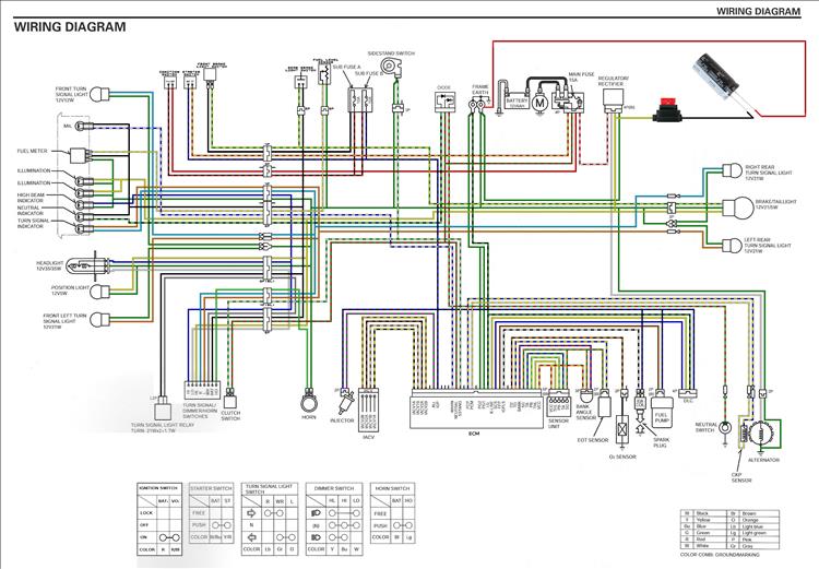
From my wiring diagram and research on the interweb I suggest the following.
The CBF125 is said to have a "negative pulsed DC" circuit for the lights. I've read this on several forums.
There are 2 wires from the stator but the green (green being the colour of "ground" or "earth" for all Honda's I've worked on) goes to earth on the frame. Why this could not have been earthed at the stator itself I do not know.
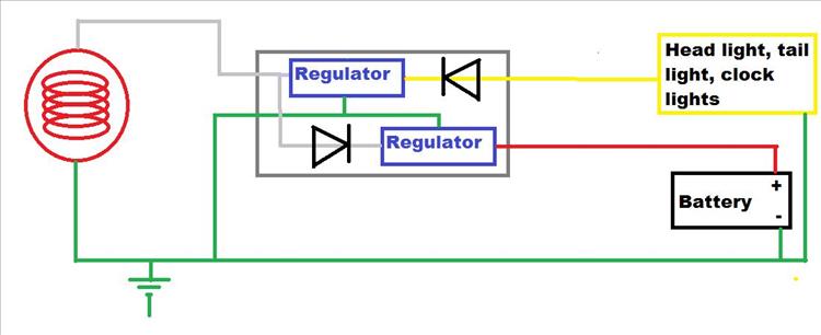
See the diagram below for what I *THINK* may be going on. Before anyone uses this information for diagnosis or repair let me make this clear - this is a GUESS!!
 15/12/2016 17:41:36 UTC
Ren - The Ed said :-
So...when current flows from the white wire (shown as grey) it flows to the reggy reccy. Due to the diodes the flow passes through the lower diode and the regulator then on to the red/yellow wire (shown as red) to the battery and thence the ECU, indicators, brake light and sensors.
When the current flows in the opposite direction it goes to earth/ground/the frame first. It then passes through the head light, tail light and clock lights returning through the reggy reccy which controls the flow. Hence "Negative DC"
Both circuits are pulsed. They are both half wave rectified only.
NOTE!! I am still guessing and I await more informed people to correct me.
15/12/2016 17:46:57 UTC
Ian Soady said :-
That looks feasible if a bit weird to my mind.
I can't see however how you can have a "negative" pulse going along your green frame / wire as that would confuse the battery - and perhaps more important the ignition system - no end. But I'm probably missing something.
16/12/2016 17:15:40 UTC
Ren - The Ed said :-
Upon further consideration I think my diagram is wrong. I am presently working on a new version but I need to understand transistors more first.
You're right Ian it would be far far far simpler to install a standard single phase reggy reccy and alter the wiring accordingly. I may do that but I've got this bee in my bonnet needing to understand what Honda has done here. And WHY!
17/12/2016 09:01:06 UTC
Ian Soady said :-
Maybe the "why?" is "just because we can"?
Honda have managed to visit some horrors on us over the years as well as some beautifully designed and executed stuff.
The cynic in me wonders whether there's some planned obsolescence going on here. "Good" design would result in everything being made to a standard where it all fails at the same time (from the manufacturer's point of view just after the warranty ends). Instead, we have components failing one at a time giving us poor deluded fools the idea that if we just fix that stator / regulator / wheel bearing etc everything will now be fine. And then of course we've sunk so much money into the old wreck that another £90 or so fades into insignificance. See the sunk costs fallacy.
www.behavioraleconomics.com/mini-encyclopedia-of-be/sunk-cost-fallacy/...
17/12/2016 15:23:49 UTC
Ren - The Ed said :-
It's an age old problem. As Kenny Rogers said "You've got to know when to hold 'em, know when to fold 'em". Personally I've never beeen good at either gambling or deciding when it's time to quit a bike.
I know what you're getting at. Throwing good money after bad as me Dad would say. Always trying to keep the old girl going. It'll be fine if I just fix X,Y and Z. 70 quid here, 30 pounds on fork seals there, 7 for new brake pads and soon it'll want tyres again.
But then wouldn't a nearly new bike want all this sooner or later? Argh! Who knows? Perhaps that's the REAL conspiracy. Perhaps they make these things such that we'll never know so we're trapped into the never ending spiral of parts and repairs and impossible decisions! Doomed!
Or perhaps some things just wear out like tyres and chains. Some things are poorly designed like CBF125 stators. Some things last for ages even though you don't expect it like the CBF125 shocks.
Ours is not to reason why, ours is to just to do and buy...the parts and keep on buying them otherwise Mr Honda and Mr Suzuki will become poor.
19/12/2016 08:30:24 UTC
Ian Soady said :-
"gambling's for fools. But that's the way I like it baby, I don't want to live for ever....."
And of course he didn't.
www.youtube.com/watch?v=sjkzbCkZEuQ...
19/12/2016 16:29:32 UTC
Ren - The Ed said :-
Yeah but considering what Lemmy put his body through with drugs, drink and cigarettes I reckon he must have had the constitution of an ox. If his body were a motorcycle it would have had 250,000 miles on the clock, been to every country in the world and been running sweet right up to the end. Shame, but not one of us is gonna make it.
19/12/2016 16:39:41 UTC
Liam said :-
Your schematic of the reg rec is correct.
The reason it is separated is to allow the battery to get charge at low RPM when there's not enough output to run the lights.
The lights don't need smoothing due to being tungsten bulbs. By not running them off the battery circuit it increases the power factor of the lighting circuit meaning a smaller, cheaper charging system can be used.
Interesting to note what we have here is a dual rail system. Anything running off the battery is negative earth, anything running off the lighting circuit is positive earth. Just like how it was on old vehicles.
On multi rail setups the term is 0v. This simply indicates a point to which we take measurements of all other voltages from to quantify readings.
If you change all the instrument bulbs to LED as well as the rear stop/tail bulb. Remove those bulbs from the yellow lighting feed and feed them off the black switched live you are only left with the main headlight bulb on the negative feed lighting circuit. This frees up enough current to allow the HS1 to be changed to an H4 headlight bulb.
I did this on mine and used a fine filament, 55/60 xenon gas filled high output bulb. The headlight is superior to what it used to be.
No signs of heat stress to the headlight and extra load puts no more load on the stator. This is due to the regulator being a parallel shunt regulator. Regardless of load the current from the stator is always the same at at any certain RPM.
27/12/2016 22:47:21 UTC
Liam said :-
Just to clarify. Your regulator schematic is almost correct. The diodes both sit at the output on each circuit. The peak voltage of both circuits are different to achieve an RMS of 14.4v due to the lights being un-smoothed.
The regulator will be an SCR sitting across the AC feed with the trigger circuits most likely being split and fed post diode on each circuit.
27/12/2016 23:01:33 UTC
Ren - The Ed said :-
Wow! Cheers Liam.
I can see the advantage of splitting the lights from everything else. One circuit for keeping the battery topped up (and thence the ECU and FI) and the other for lights.
I'm curious as to how you know this? Electrical engineer, motorcycle hacker, experience? I kind of guessed with my limited auto electrical knowledge and common sense.
The subtle problem with the CBF 125's curious setup is the "bespoke" reggy reccy. It's not like we can throw on a random spare from a friend and it will work.
28/12/2016 08:52:36 UTC
Liam said :-
It's from working on bikes coupled with knowledge/exoerience in electronic engineering.
Been a while since I've had an EFI ANF125 in the garage but IIRC they use the same configuration.
If you do a lot of out of town riding or don't spend long amounts of time in traffic there is an option.
Where the green wire is on the stator you can see it also connects to a lug that connects it to the engine earth. Because of this you can't use a full bridge rectifier set up as trying to do so would cause every negative cycle of the AC waveform to short through the rectifier.
If you disconnect the enameled wire at that point and connect it to an insulated wire that connects to no other aside FROM a rectifier, just like the white wire does then you can use a standard single phase reg/rec. Like the one linked below.
Floating AC in connects one wire to pink, one to yellow.
DC positive out is on red.
DC negative out is on green, this becomes bike "earth".
Black is a voltage sense wire, connect this to switched 12v which on the CBF125 is also black.
After doing this you can connect the now unused yellow to the battery positive via.....
10 amp fuse, into a SPST relay input, relay output to yellow. The relay coil connections go one to earth and one to black switched live.
That will give you a full DC set up as well as charging of the DC system on both halves of the AC waveform.
It is imperative to float the stator output, if either winding is referenced to frame a short circuit is created in the regulator/rectifier.
Done this mod a few times on small Hondas. Didn't do it on my CBF as I'd just changed the oil when I decided to improve the lighting.
This is the reg/rec I mentioned above.
http://www.ebay.co.uk/itm/12v-Chinese-Taiwan-Scooter-Quad-Bike-ATV-RECTIFIER-REGULATOR-125cc-Sukida-T-14-/172459926417?hash=item282769a391:g:3OYAAOSwgmJX1pxg
I also wrote an article on winding your own stator for the C90 forum. The BBcode somehow turned off for some reason so the pictures only show by manually pasting the URL into Google. It could do with refining a bit but I don't have edit powers. It's also not where it should be but anyway, if you're interested here's the link.
http://www.c90club.co.uk/viewtopic.php?f=14&t=24581
28/12/2016 10:33:32 UTC
Ren - The Ed said :-
Cheers Liam
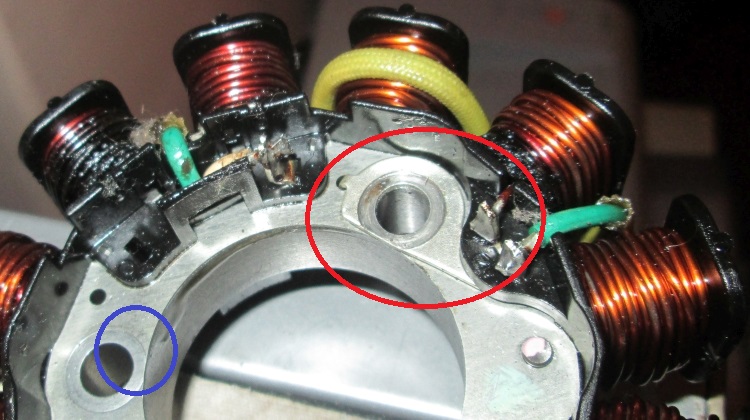
I did wonder why there was a peculiar tang thing (circled red) on the stator. That takes what is essentially one side of the windings and sends it to earth-the motor-the frame. I've metered it and it is connected to the green wire.
I never thought the inner ring of metal (part of this is circled blue) was NOT conductive. I've metered it and I can't get any connection through it. Hence the tang to connect to the presumably conductive bolt to connect to the engine.
So if I were to remove the tang I wouldn't need to fit a wire, I could simply use the green wire as the "other" end of the windings wire.
Liam - if you'd be interested I'd love to put something on my site regarding both subjects. Firstly the option to convert the CBF125 into a more typical single phase setup and secondly DIY rewinding. The stator in the image is my original that gave up at 30.000 miles so is "spare". It would be handy to rewind this myself and keep it for future use.
If you're interested drop me a line - ren@bikesandtravels.com
 28/12/2016 19:08:47 UTC
Paul said :-
Your knowledge is hugely appreciated
18/04/2017 20:19:18 UTC
Ren - The Ed said :-
Cheers Paul! Erm, which snippet of information was of particular use?
18/04/2017 21:15:28 UTC
Abhishek said :-
Very useful information.
There is something I would like to add. On the indian version of CBF125 (Known as Honda Stunner) the green wire from stator is connected to the ground at 2 points for some reason. 1st at the stator itself, and 2nd somewhere inside the wiring harness. To install a full wave rectifier, the rectifier input wires need to be connected directly to the 2 wires coming out of stator (thus bypassing internal wiring harness) otherwise the rectifier won't work. I know this because few years ago I purchased a new full wave rectifier for my CBF, I was confused when I couldn't get it working right at the first attempt. Had to revert back stock rectifier unit. Then one fine day I decided to try installing full wave rectifier once again, this time I connected rectifier input directly to the 2 wires coming out of stator and IT WORKED!
11/09/2017 23:45:09 UTC
Ren - The Ed said :-
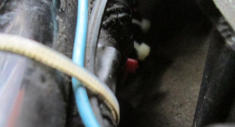
Cheers Abhishek! You're spot on. In my picture you can see the green wire goes to the engine which is earth, the other end goes to the frame up behind the fuel pump! Seems like overkill to me but hey-ho.
I have seriously considered the full wave rectifier option simply because they are very common and cheap to purchase. How are you doing with yours?
12/09/2017 06:11:05 UTC
Abhishek said :-
My full wave rectifier is doing well (been 3 years so far). After installing a full wave rectifier, the running lights won't work anymore so I made some changes to the wiring. My lighting circuit (red wire on Indian CBF or yellow wire on UK CBF) is now connected to the ignition live wire.
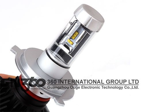
I also upgraded to a 55W Philips Xtreme Vision bulb - and noticed a significant improvement in illumination compared to stock 35W bulb. The new full wave rectifier could easily handle the bulb upgrade , which wasn't the case with stock rectifier. Still in the quest for more light, recently I got a 25W LED headlamp bulb which is even better than the 55W Philips halogen bulb and the white light from LED looks awesome on the road.
https://www.aliexpress.com/store/product/CN360-2PCS-X3-9006-HB4-LED-ZES-Chip-All-In-One-Car-Lamp-Fog-Bulbs-3000K/2061060_32812412060.html
12/09/2017 07:31:53 UTC
Ren - The Ed said :-
Yeah because one half of the wave fed the battery and the other half the lights. If you rectify both waves onto the battery there's no half wave for the lights. In which case the lights need connecting to the battery.
Does the halogen bulb work with the lens ok? I don't know where you live Abhishek but in the UK the MOT inspection checks the shape of the light output on dip beam. I'd like to know if the new bulb changes this.
12/09/2017 16:12:10 UTC
Ren - The Ed said :-
Dammit not the halogen bulb I mean the LED bulb.
12/09/2017 16:13:07 UTC
Abhishek said :-
There is a slight variation in the beam pattern, but it is very similar to halogen. Unlike other cheap LED bulbs, this one was specifically designed to emulate the halogen beam pattern. With some adjustments (screw at bottom of headlight + adjustment feature on bulb) I am sure you can pass MOT inspection, otherwise just revert to stock halogen bulb on the day of inspection and switch back to LED once it is finished.
Philips - one of the leading automobile bulb manufacturers also officially makes LED H4 bulbs and the design is very similar to the Chinese LED bulb I am using. The Philips LED bulb is quite expensive though, this Chinese LED bulb is much cheaper, uses good quality components and performs equally as good as the Philips LED bulb if not better.
 12/09/2017 17:23:45 UTC
Ian Soady said :-
It's highly likely the Philips bulb is made in China anyway.
13/09/2017 10:23:01 UTC
Ren - The Ed said :-
It's tempting to try the LED option but I'd certainly have to also do the full wave conversion. I know from experience the LEDs don't like the wobbly half rectified electrickery.
Some really useful information Abhishek, thank you kindly.
13/09/2017 19:14:04 UTC
Cx said :-
Hi Guys ,
I am trying to use LED on cbf 125 .. I am really confused how the connections should be done , Could you please check the wiring diagram I made and tell me if this will work? thanks!
https://photos.app.goo.gl/Dzia3Lj6mZddmQVZ7...
 29/09/2021 11:08:59 UTC
Ren - The Ed¹ said :-
Cx - I do not consider myself an electronics expert as such my advice comes from a position of limited knowledge.
But - I'd recommend not trying to install LED bulbs without some serious expert advice.
Most motorcycle's lights are powered from the battery, the battery being charged from the alternator. Not so the CBF125 (note CBF125 not to be confused with the CB125F). The lights are powered directly from the alternator using 1/2 of the output of the single phase alternator - the other half is used to charge the battery that then runs the computer and rear brake light.
As such the power to the bulbs is "jerky". Instead of a battery providing a smooth constant flow of electricity to the bulbs the CBF125 feeds rapid pulses of electricity. An old style bulb (incandescent) can handle this as it merely heats up and glows anyhow. I have used small push fit LED bulbs for the side light and they have given up rapidly. I would suggest LED's need a constant and stead flow rather then a rapidly pulsing flow.
I believe it is possible to wire the CBF125 such that it runs similar to most other bikes. But I don't know how to do this and I'm not entirely sure of the long term consequences of such a set up. It is beyond my electrical knowledge and unless you are particularly skilled in such matters I advice caution. At the minimum you risk damaging the expensive LED bulbs, at worse you could damage the bike's charging system.
29/09/2021 18:03:31 UTC
Cx said :-
Thanks for the response .Now I have 2 led fog lights 25w total which are powered through the fusebox with a fusebox thief which powers the switch for the fog lights. I have them for 5 months and I had no issues.
I am just thinking to make all lights LED since they consume less and there are way brighter than halogen.
In the above diagram I have a bridge rectifier which takes both waves and then sends the power to a DC-DC regulator booster which limits the voltage to 12V (it takes 8-40V as input) and amps to 10 .If the voltage is stable at ~12V i believe led will run fine . The only issue is than I cant find someone to comfirm my diagram and at the posts above I read that I may short the regulator ..not sure?
With the knowledge you have on electrics and on this bike do you think it will work?
Thanks
 30/09/2021 19:05:51 UTC
Cx said :-
By the way I got most of the idea from this guy https://www.youtube.com/watch?v=l-4Snr1sia8&t=1169s . Unfortunately he is an indian I dont understand what he says haha
30/09/2021 19:12:28 UTC
Ren - The Ed¹ said :-
You'll have to bear with me Cx.
From your diagram - 2 wires from the alternator, green goes to earth and grey goes to the reggy reccy. From the reggy reccy you take the yellow wire and grab the earth from, well, an earth. I believe you should have used the grey wire. The yellow wire feeds the light circuit and is already regulated and rectified to a pulsating -12v and is no use to you. The grey wire from the alternator is the unregulated and unrectified wire.
I presume you are aiming for 2 regulator rectifiers? The one already fitted and the one you are adding for the lighting circuit. As such you'd need to split the wire from the alternator to feed the 2 reggy reccys.
This leads me to wonder then. You'd have to be sure the reggy reccy YOU are adding only grabs the negative part of the sine wave from the alternator. Otherwise the alternator will be feeding both the battery and the lights from the positive part of the alternator which, even with LED, would be a strain.
Personally I'd be looking to smooth out the -12v output from the existing reggy reccy. Capacitors or a small 12v battery?
I'm not knowledgeable enough to know how many farads you'd need, or how to wire this up. Tread carefully Cx.
01/10/2021 09:49:18 UTC
Cx said :-
HMMMMMMMMM.. you got me in deep thoughts and I am afraid that you are correct and I will have to the change plan :P
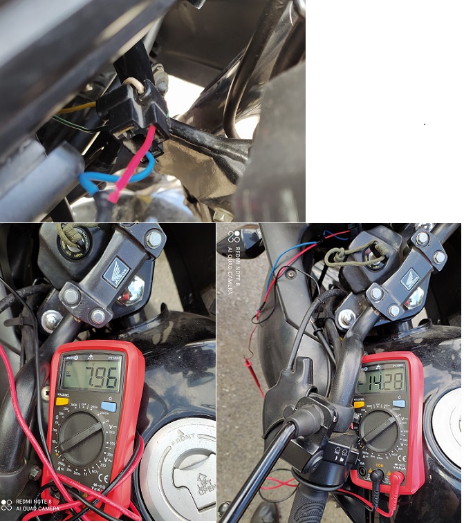
I bought a capacitor 63V 2200uF for 3 euro which I tried to use .
I tested the H4 input wires for the main light, Green and White (LOW BEAM ) wires . Without the capacitor the DC voltage is ~7.96V DC on idle and when revving the engine it drops to ~3V DC.
With the capacitor on idle ~14.28V DC and when revving ~13.8V DC.
I tried to connect an H4 led bulb which normally flickers a lot on idle .. and the flicker was almost gone ! !
 01/10/2021 13:23:50 UTC
Cx said :-
By the way I cant understand why the voltage drops to ~3V when revving.. Do you?
01/10/2021 13:36:54 UTC
Ren - The Ed¹ said :-
You're in a world of which I only have a basic understand Cx. Electrickery is the dark arts as far as I'm concerned.
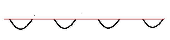
I'm wondering if the volt meter is struggling with the pulsed DC. Bear in mind the DC being fed to the bulbs is pulsating. And it is only half a wave. This means - ahem - for every sine wave from the alternator the bulbs receive nothing for 1/2 the cycle then a rising then falling pulse, then nothing, then a rising then falling pulse. As the multimeter is designed to, at worst, receive a smoothed out or perfectly smooth and steady flow of electrons then your meter is like "what the hell". I'd be looking at a oscilloscope if I wanted sensible usable readings. There are add-ons for smart phones these days, quite cheap and quite usable I'm told.
I would then suggest the capacitor is smoothing the flow to the point where the multimeter can make sense of the flow of electrons. As for what size/type of capacitor you could/should use? I have absolutely no bleeding idea at all. Probably a big one.
This is the pulsating negitive DC your bulbs will normally recieve...
 01/10/2021 16:05:28 UTC
Bob said :-
Ren is correct.
If you switch your meter from DC to AC you will see that the as the DC drops the AC increases.
Keep in mind that the meter will show you a smoothed average of the DC voltage applied and in AC mode it's more complex because it is designed to show the RMS value of the AC voltage (some meters are "true RMS") at 50Hz, not at the frequency of what's coming out of that alternator.
An oscilloscope is the only way you will be able to truly see what's going on.
03/10/2021 08:41:17 UTC
Cx said :-
I see . Unfortunately the 63V 2200uF it seemed ok during the day but when I tried it at night still flickers a lot :(
I will buy 2 x 10.000uf capacitors and also I have ordered this ( https://www.aliexpress.com/item/32518056747.html?spm=a2g0s.9042311.0.0.27424c4dRD9v7Y) DC-DC 8-40 step up 12V10A converter which I will have next week..
I am not sure if the DC-DC converter reduces the ripple to an acceptable number so LED run without flicker, but from what I understand it should stabilize the current to 12V as it takes as input 8-40V .
Hopefully a combination of 2 x 10.000uf capacitor and also DC-DC converter and of course a fuse will work !!
Do you think it will be an issue that is negative voltage? if understand correctly negative voltage can be used without issues for what i am trying to do..its just the excess voltage which is not used for the battery i guess?
03/10/2021 21:56:55 UTC
Ren - The Ed¹ said :-
Not being an electronics whizz I'm unable to say if it will work or not and I really don't want you to fry something! Please be careful.
Do you understand how the alternator puts out alternating current and what alternating current is?
04/10/2021 08:33:47 UTC
Cx said :-
I believe I do . Ac is the same current we have in home and use adapters to convert to DC in most cases.
Alternator produces ac through the coil and feeds regulator rectifier which converts to DC pulsed and charges the battery to a limited voltage so it doesn't destroy it .The remaining current goes to the lights ;Any excess current which is not used is "removed " as heat from the regulator .;
04/10/2021 11:10:11 UTC
Cx said :-
I bought today 2 x 10.000uf 63V capacitors . I hardwired them in the h4 socket to check if the flicker is gone...and VOILAAAA the flicker is gone completely !
In the next days I will wire them to the switch so they work both for low and high beam.The DC-DC converter may not be used at all.
04/10/2021 18:50:20 UTC
Bob said :-
Well done.
I would leave the DC/DC out, you'd probably find that high frequency input transients would upset it anyway - internally it is a switch mode supply and line regulation is typically not too good as a result.
05/10/2021 11:41:45 UTC
Ren - The Ed¹ said :-
Thanks Bob. I don't really know anything about DC/DC outs. I'm off now to learn about capacitors and how to "specify" them.
05/10/2021 14:52:48 UTC
Cx said :-
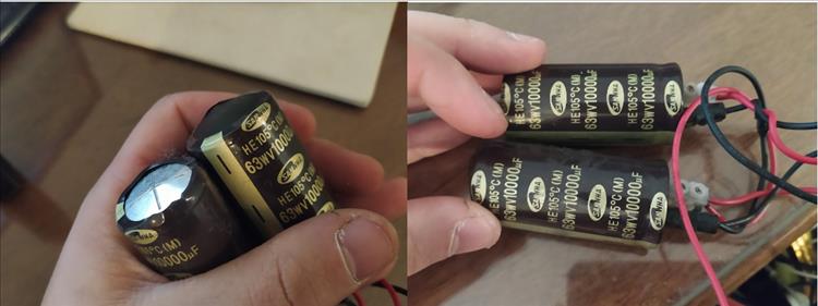
Damn.. I tried to ride today with the capacitors, like was working fine and after 30 minutes I checked the capacitors and they were very hot and the bottom was inflated . Not idea why would this happen..connections were correct.
 09/10/2021 14:41:00 UTC
Ian Soady¹ said :-
Those look scary. I haven't read through this thread thoroughly but there's definitely something amiss. Big capacitors can hold an enormous charge - it's worth getting rid of it before you touch anything with your fingers by shorting out the terminals with a screwdriver - holding the well-insulated handle of course.
09/10/2021 16:43:53 UTC
Cx said :-
They are not so powerfull , could light up the LED 25W for 1 seconds at full power and 6-10 seconds dimmed.
I believe it has to do with the ripple or the negative voltage..I have tested them on stable DC and they were working fine .
I am really dissapointed that it did not work pff
09/10/2021 17:09:15 UTC
Bob said :-
Those capacitors have either been exposed to over-voltage or negative voltage.
Be careful, they can go with a heck of a bang and are capable of causing injury.
The only way you will figure out what's really going on is with an oscilloscope.
11/10/2021 08:02:34 UTC
Ren - The Ed¹ said :-
Yikes! Them capacitors look unhealthy.
The problem is Cx is I am not an electronics expert and I suspect you're not either. I'm just a chap with a little knowledge on how electrical stuff works and oft times a little knowledge is dangerous. Capacitors are dangerous, that much I do know. As Bob said they can go "BANG" and they can also give you a severe and possibly fatal shock. You are playing with fire here. It is also very possible you could damage the electronics of the motorcycle too.
So your quest for LED lighting could cost you some very expensive parts on your motorcycle, it could cost you some personal injuries or worse too. Is it worth it? Either seek the help of someone who is very knowledgeable of electronics, in particular motorcycle electronics, or use the standard set up while you take the time and effort to learn these things yourself.
11/10/2021 09:11:23 UTC
Cx said :-
Yeah I am not ..will talk in the next day with an electrician to see what I can do
13/10/2021 17:09:42 UTC
Ren - The Ed¹ said :-
Do let us know if this elechicken can help and the outcome. Cheers Cx
13/10/2021 19:59:39 UTC
Cx said :-
Finally found out the solution with the help of an electrician (Miktecrep on youtube).
The yellow wire coming out of alternator has negative pulsed DC , you need to connect the negative side of the capacitor(25V 10.000uf) with the yellow wire and the positive side of the capacitor to the frame .
You must also use an inline fuse 5-6Amps .
Without the capacitor on idle I was getting 7Volts DC ,with the capacitor 12,3-12,25V DC.
Led now works without any flicker both on low and high beam.
 08/11/2021 12:03:42 UTC
Cx said :-
You can find the diagram in High quality here https://photos.app.goo.gl/LneBLG6VhNfjvmLZ6
https://photos.app.goo.gl/LneBLG6VhNfjvmLZ6...
08/11/2021 12:05:01 UTC
Cx said :-
Correction **
"The yellow wire coming out of alternator " I mean regulator rectifier.
08/11/2021 12:07:02 UTC
Upt'North ¹ said :-
Well done CX, looking at the diagram it looks as though "it's easy when you know how".
Upt'North.
08/11/2021 13:14:36 UTC
Ren - The Ed¹ said :-
This is why we need help from people who actually understand this stuff! I'll take a closer look at the diagram, good info CX thanks.
09/11/2021 14:36:09 UTC
Cx said :-
Yeapp.. definetely worth it to do it if you ride at night like I do !
 13/11/2021 18:01:35 UTC
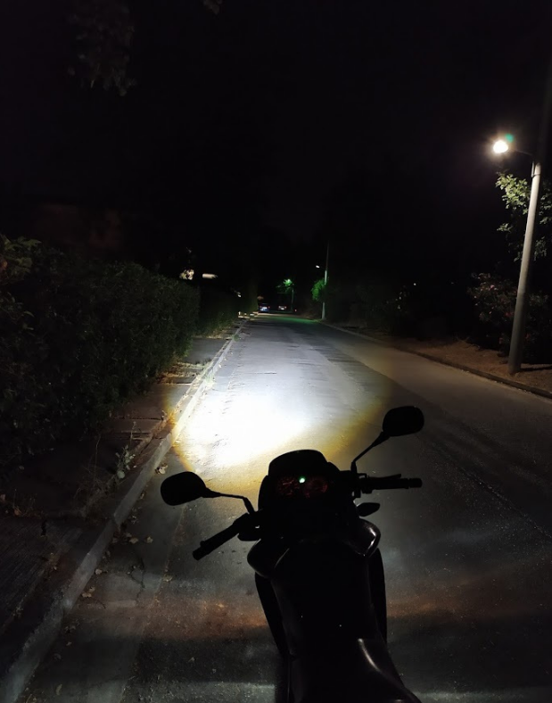
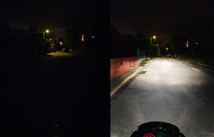
Ren - The Ed¹ said :-
Cor! It's like blummin daylight. It's hard to be sure from the image but it appears you have a reasonable beam pattern there too - have you checked it to ensure you're not blinding the populous? One concern levelled at some aftermarket LEDs is that the "point" from where the light emits can be out of position in the reflector which messes up the beam pattern.
What type/brand/model of LED are you using CX?
15/11/2021 08:37:33 UTC
Cx said :-
Light pattern is the same as halogen with a better cut off line . It cant be seen on the picture maybe because it is slightly uphill or because of the camera settings but the light pattern is like this.
Yeah I have adjusted the headlight to it doesnt blind other drivers . Have never been flashed and when I am behind a car it is always way lower from the mirrors ,it blinds a bit only when you accelerate hard and rear forks are compressed .
The bulb I am using is a nighteye - novsight 25w h4
 15/11/2021 13:04:53 UTC
Ren - The Ed¹ said :-
Good show Cx - there's far too many vehicles out there with incorrectly adjusted lights and with the modern LEDs being super sharp and dazzling it can be a real issue.
16/11/2021 11:34:35 UTC
said :-
09/07/2026 09:08:54 UTC
Name
Comment
Add a RELEVANT link (not required)
Upload an image (not required) -
Uploading...
Home
Repair And Restoration