Home
Repair And Restoration
Wiring Loom Mysteries
Job Date 23 Mar 2019
By Pocketpete
I've finally had a bit of time to sit down and get the wiring loom sorted out. Firstly the one I bought for less than a tenner was a meter too long and it also had no positive feed wire from the bike's ignition. Although the relay did have a feed from the handlebar feed system.
The switch was rubbish and designed to be put into a dashboard. I picked up a MCTuning switch made from CNC Alloy with a LCD activated light. The switch has 3 wires, not sure how 3 wires work.
Found my wire stripper and crimping tool. Had to order some heat shrink £4.99 Amazon and a few spade connectors. Also a fuse box for £3.99, good old Amazon.
Now if only I could remember how to crimp. I stripped off the fairing (again) and planned how to do the wiring. I decided to start from the battery and work forward
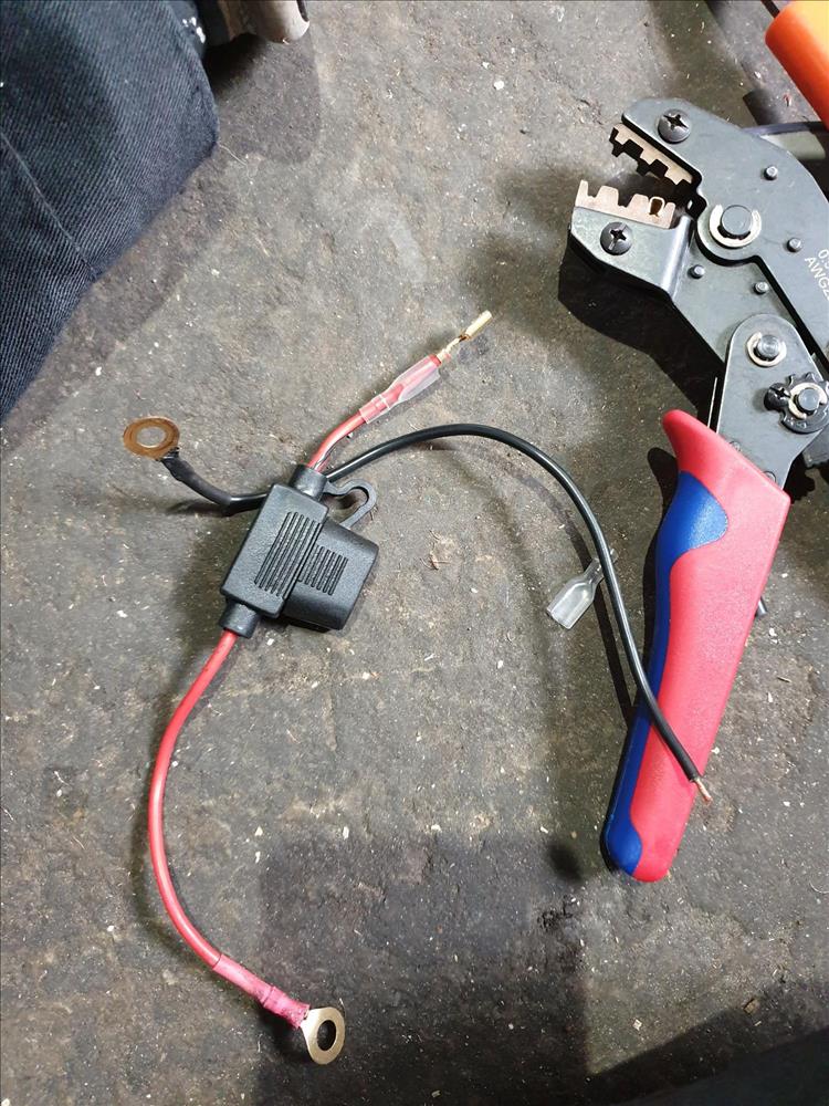
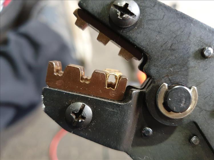
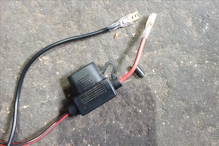
I crimped the inline fuse. Its armed with a 10amp fuse. Not sure if this is the right one but I can always change it. Just about remembered how to crimp, it's a touch tricky to get the insulation trapped and the cable in the slot.
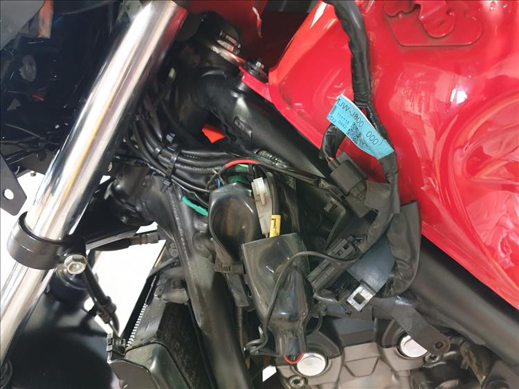
Hmmmm. Next job - run the cable to the front. I try a few different routes. The best is down the left, tucked under the side. I fed it around the frame and under the tank and out at the headstock where all the other cables run.
I have nearly a metre of spare cable so nothing for it but to cut it off. I then fit the switch to the handle bars. It fits OK, it is 22mm and is a touch awkward to get the Allen key under it but it seems securely fixed.
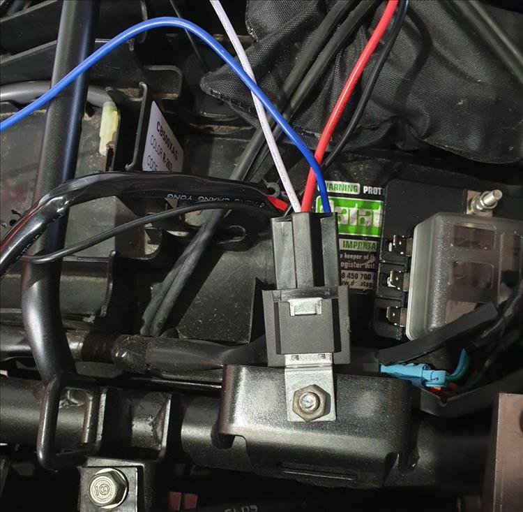
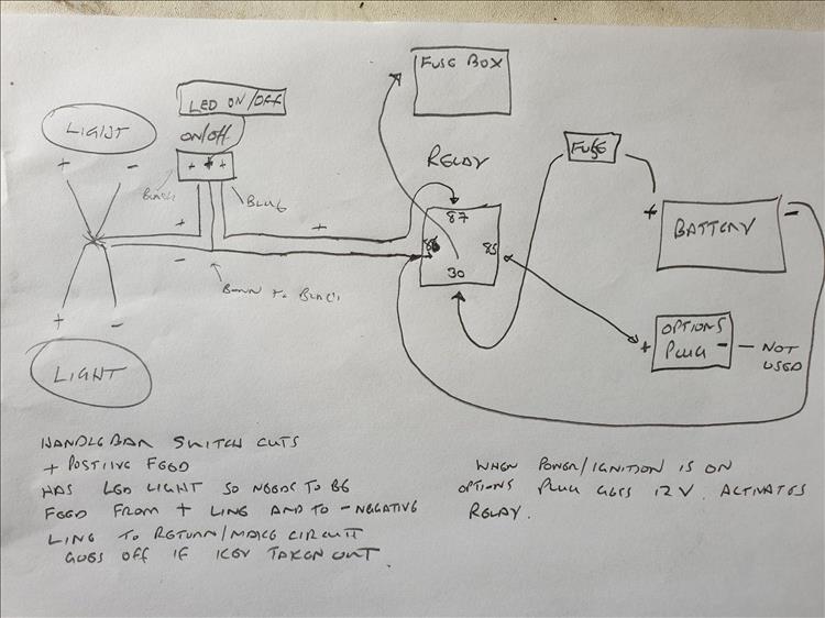
This has 3 wires but no instructions, I presume it operates as light switch. So how does it wire? I presumed that the switch cuts the positive wire. So I wire it with the two outside contacts blue and black as a break in the red main wire.
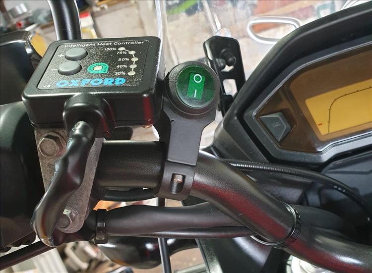
Not sure how the third wire works. It's supposed to light up. Eventually I realise it needs to be attached to the negative feed. The blue will give it power as long as the ignition is on. The negative will then illuminate the switch led light. I wire this in next. Seems to be right. I put the inline fuse in and power up. Nothing happens. I switch the button to one and it lights up.
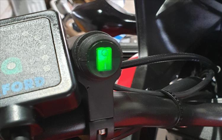
Oh what a lovely green light.
Now I will mount the relay on a suitable spot and install the fuse box. I shrink wrap the option plug. I have a white earth and blue positive spare from the relay which I will put directly to the fuse. These were from the original switch which I have cut off. That's handy the relay will do 40amps. So I can wire a couple of items to the fuse box and still have a spare options plug socket on a separate circuit.
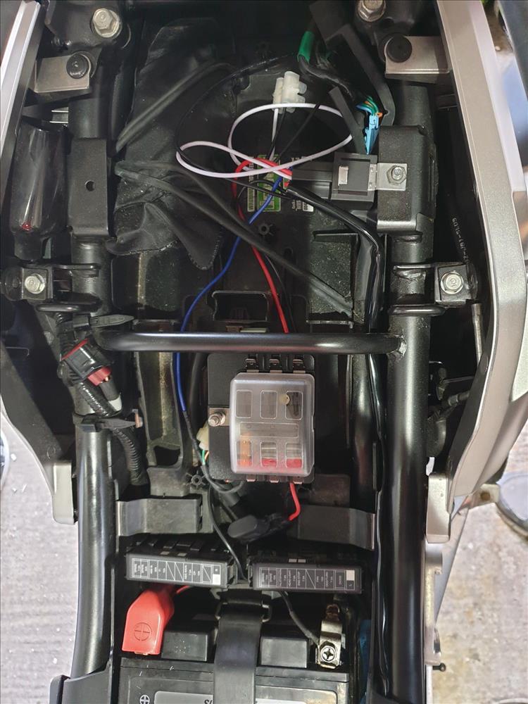
Fuse box seems ok but I wont wire it up today - my main aim is to get the lights working.
I crimp the switch in and cable tie the main loom to the cables by the headstock. Then I fabricate a connection to the lights and run it back across to the headstock. I have to heat shrink the exposed sections and it's all a bit cramped but I end up with a reasonable job.
I turn on the lights, not working, what's going on!? Ah crap durrgh they work better if you wire a negative in. I duly fabricate a matching negative loom to the lights and bingo the lights are working.
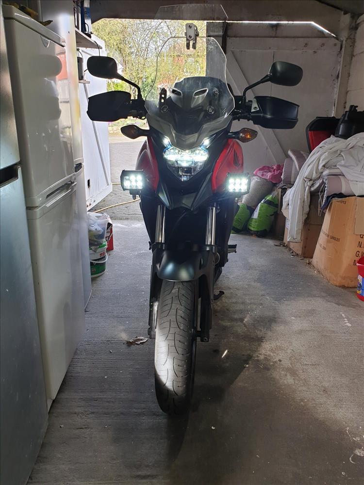
The switch lights up and turns off the light. They only work when the ignition is on. I'm a happy bunny and it only took 2 hours. Total cost of the lights, mount and wire relay fuses around £70. Quite happy with that as Honda ones are £300 and Denali ones are £259.
Ive draw a bit of a guide it sort of helped me get my head around it all. Might be useful to someone.
Next jobs - new horn, GPS mount, GPS, USB, 12v cig lighter. Let the farkling go on and on.
If you'd like to sponsor a Bikes And Travels page then contact ren@bikesandtravels.com
Reader's Comments
Name
Comment
Add a RELEVANT link (not required)
Upload an image (not required) -
Uploading...
Home
Repair And Restoration